I’ve finally started settling into my new job a bit more, and the huge waves of feeling overwhelmed have turned into small ripples, so time to step up the blogging again!
One love I’ve cultivated a lot over the past few years is that of EE. Designing circuits and building them is just a lot of fun. It’s almost like getting to program with physical objects and connections instead of code. At least that’s how I view it, though I’m sure the electrical engineers out there are rolling their eyes.
I like designing and working on complex digital circuits, but it’s also fun just to make quick, neat little projects. Often times they have more uses than you’d even think of.
Annoy Your Friends!
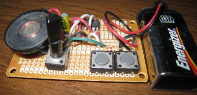
One I made a few years ago for a yankee swap gift (I made two, kept one for myself), was what I called the “Super Noise Maker 5000”. In truth, it was just a variable tone generator. I put a nice loud microspeaker and a pot on it so you could basically drive people nuts with a nice loud noise that you could twist from low to high pitch over and over again. I even put a 1/8″ mono jack so you could pump the volume up through an external amp. 😉
Specs
Aside from annoying people, tone generators are pretty neat and have a lot of uses. Tracing lines, telcom uses, music generation, etc, they’re just a lot of fun. While the specific application you’re designing it for dictates what kind of control you have over which frequency is produced, for our purposes, we want a fun toy, so the Super Noise Maker 5000 does the following:
1. Uses a 9 volt for power (this lasts a long time, this circuit doesn’t use much juice)
2. Has a push button to activate the sound (press the button, hear the tone!)
3. Has a potentiometer to control frequency (turn knob right, lower frequency, turn right, higher frequency)
4. Has a second push button to change octaves (well, not an exact octave, but if the button isn’t pushed, its lower frequencies – push the button, it jumps to higher frequencies – you can get some awesome effects tapping this button while adjusting the frequency)
5. Has a 1/8″ mono jack for piping the sound out to a receiver/amp/recording device/whatever.
6. Onboard speaker hits high frequencies VERY well and it hurttttsss. I don’t do this too often for both my and my cats’ sake.
How Sound and Speakers Work
The theory behind this is pretty easy and is a good starter project. First off, remember that sound is a pressure wave – it is the movement of air at a frequency – these pressure waves hit your eardrum, and you hear sound. Higher frequency, or more waves per second, is a higher note – lower is lower. So speakers operate by vibrating, which produce these pressure waves at different frequencies. The speaker vibrates by the magic of magnets. Since magnets can either attract or repel each other depending on the polar orientation, speakers use this by having one permanent magnet that is always aligned with a specific polarity and an electromagnet that gets its current polarity from running current in a specific direction over it.
So if we run current back and forth over the electromagnet in the speaker at 1000 times a second, we get a 1000 hz, or 1khz tone out of the speaker. If we make the electromagnet switch poles 5000 times a second, we get a 5khz tone. Etc!
Now, the problem arises that we need to turn the steady voltage from our battery into an oscillating amount. If we just ran steady DC power over a speaker, it wouldn’t do anything except damage the speaker – the electromagnet would just stay at the same polarity, hence no sound. We need to take that steady stream of electricity and turn it into a wave, so it moves the magnet back and forth. There are a lot of ways of getting oscillated power, some are geared toward fixed amounts, but we want a variable amount (we want to control the frequency of oscillation). An awesome little chip to do this is the 555 Timer, one of the most multipurpose chips EVER, it’s great.
The 555 Timer
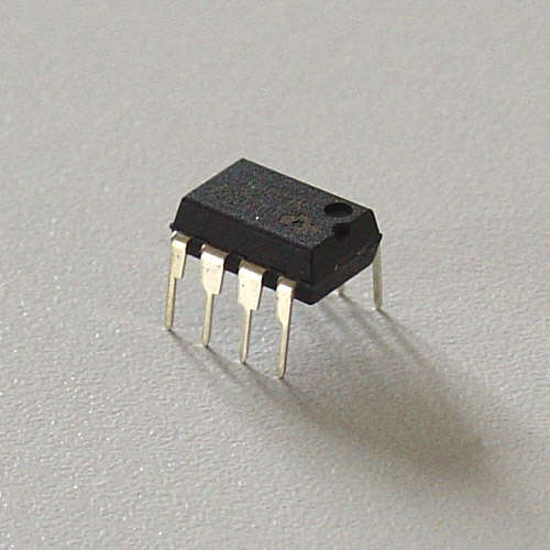 The 555 timer family (when in astable mode, the 555 timer has multiple uses) takes steady voltage, say from our 9 volt battery, and pumps out a square wave, or in other words, oscillates back and forth between 0 volts and 9 volts. The frequency is driven by the use of resistors and a capacitor across its control pins – which we can control. We can either use specific resistors for a fixed frequency, or we can use a potentiometer and have a user controlled resistance, and hence frequency. There are lots of 555 timer calculators online too for figuring out what values to use for the desired frequency.
AC/DC
We still have a small problem though. Our 555 is putting out an oscillation between 0 and 9 volts. This isn’t quite what the speaker wants – instead of driving the electromagnet back and forth, we’re driving it in one direction and then turning it off over and over again. While this does make a sound, it’s not a clear sound or at the right frequency (and I’m sure not so great for the speaker). We need to turn this oscillation in DC current into AC current, i.e. instead of 0 to 9, we want -9 to 9. We want the current to go back and forth equally in both directions, not just in one direction and then not at all.
We can do this with a capacitor. Remember, a capacitor acts kind of like a little battery that can charge and discharge quickly – we can charge its terminal, and when current is removed, the capacitor discharges. This means that it will either draw or discharge current depending on if you are charging the other terminal. Hence if we put the capacitor between our 555 and the speaker, when the 555 pushes out 9 volts, the capacitor will charge and pull the current in one direction, and when the 555 goes to 0, the capacitor discharges and pushes the current the other direction. This causes AC power, since it oscillates between positive and negative, which is exactly what our speaker needs. And since it’s driven by the 555 timer, we get the correct frequency!
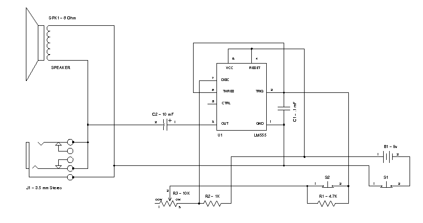
The Schematics
Here is a (somewhat messy, I’ve gotten better at circuit diagrams over time) schematic of the device. You can see I’ve used an LM555 timer, a speaker, stereo jack, a couple resistors, a couple buttons, a potentiometer and a couple capacitors. While this is a fun, neat little circuit to build, feel free to expand on your own and make your own ways of controlling the frequency, or combining tone generators together for multi-tone fun!

 Hello - and thanks for visiting my site! I maintain ToniWestbrook.com to share information and projects with others with a passion for applying computer science in creative ways. Let's make the world a better and more beautiful place through computing! | More about Toni »


dear! thease circuits are very useful for stusents & hobbiest. i like this circuit
Thanks for the kudos Yogesh!
Thanks!! very useful hope to build one soon
Thank you…I am beginning to research different ways of making tone generators and these seems very straight forward. I was wondering what the frequency range is, i.e. how low and high this circuit can go. I have a few more questions if you are willing to help me out, that would be greatly appreciated.
cheers
Very cool, just built one to act as an electronic dog whistle. Thanks for the helpful explanations!
Hello, What is the frequency range, I ‘m looking for something that will get up into the inaudible range
thank you so much will make it tomorrow..need a bread board ..thanks 🙂
abhirup from kolkata (calcutta) , india
Great stuff! 🙂
Thanks for sharing.
To people who want to build this note: C1=100nF, C2=10uF.